August 20 2019
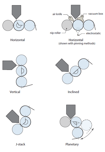
Roll Stack, Sheet Stack, Roll Stand, Take-Off System, Casting Machine, these are just a few of the terms that the plastics processing industry uses to describe the equipment immediately downstream of a flat die on a film or sheet extrusion line. Regardless of the term used to describe this device, it’s basically an arrangement of heat transfer rollers designed to cool and shape molten polymer after it has been extruded through a die to form a continuous web of film or sheet. There are many possible arrangements of the rollers, but the most common are horizontal, vertical, inclined, J-stack, and planetary. What are the differences and why would one configuration be used over another?
As you can imagine, there are many variables that must be considered when designing this equipment. Which polymer(s) are being processed? What is the throughput and desired line speed? What kind of surface finish is desired?
Polymers have a wide range of thermal and mechanical properties – melting point, viscosity, melt strength, specific heat, thermal conductivity, modulus (stiffness), thermal expansion, etc., not only between general families of polymers – e.g. polypropylene (PP) vs. polyethylene terephthalate (PET) vs. polystyrene (PS) – but also over the normal range of process conditions from the molten state to fully formed and cooled to room temperature for any particular polymer grade. Thermal properties when combined with throughput, thickness, and line speed will generally determine the number of rollers required and the corresponding roller diameters.
How we transport a molten polymer with low viscosity and melt strength (picture a thick liquid like honey) from the die lips to the surface of the rollers will be different than for polymers that have high melt strength (something approaching the consistency of sliced deli cheese coming off the slicer). For higher melt strength polymers (e.g. PP), vertical roll stacks may work well as the molten polymer will be able to bridge horizontal the gap between die lips and roll surface. For low melt strength polymers (e.g. PET), however, horizontal or inclined roll configurations may be needed to allow the molten polymer to flow almost like a waterfall vertically downward onto the roll surface.
For good heat transfer from the polymer melt (and ultimately finished property uniformity of the web being produced) it is important that the polymer melt be in close uniform contact with the rollers. Often this is accomplished with a nip roller as is used in a traditional 3-roll vertical roll stand with a web path from top to bottom. The top roller in this configuration has very little contact with the web and doesn’t transfer much heat but can apply significant force “pinning” the polymer melt to the middle roll where the bulk of the cooling can take place. It also can provide a certain degree of gauge control by maintaining a precisely controlled gap between the rollers. In other configurations, the pinning may be accomplished with an air knife or electrostatic pinning band/wire, both of which apply less pinning force than a nip roller and are typically employed in horizontally configured casting machines. If line speed is relatively high, air entrainment under the melt can be problematic, especially for air knife and electrostatic pinning systems. In this case, a vacuum box can be used to aid in the pinning action by applying a vacuum to the back side of the melt curtain as it is extruded onto the primary casting roll, increasing the effective pinning force of these systems and ensuring uniform contact with the heat transfer roller.
If a glossy surface finish is desired for both sides of the web or if a glossy finish is desired on one side and an embossed pattern is desired on the opposite side, it is critical that the opposite side hasn’t fully solidified by the time it reaches the polishing/embossing roller on the back side of the sheet. This implies that there will exist an optimal amount of wrap on the first casting roller for any given set of process conditions (polymer, thickness, line speed, roller temperatures, etc.) to provide cooling on the first side but not completely through the sheet. In the design of most roll stand configurations, the amount of wrap is fixed and is a function of the layout of the rollers. A typical vertically arranged 3-roll stand typically provides approximately 180 degrees of wrap on the middle roller (the primary cooling roller). A horizontal or J-stack configuration may provide more wrap, but the amount of wrap will still be relatively fixed, limiting the flexibility of the system to process a variety of process conditions. This is where a planetary design in which the second cooling roller position varies “in orbit” around the primary cooling roller can be used, allowing adjustments in the amount of wrap on the primary cooling roller depending on the position of the secondary cooling roller.
There are other factors that are used to determine the optimal roller configuration for any given film/sheet extrusion line application. Hopefully this article has provided some insight into why so many different configurations exist along with a few common examples of why one configuration would be used over another. An experienced machinery OEM should be able to provide you with a range of options based on your application and provide the guidance needed to choose the optimal design for your application.
